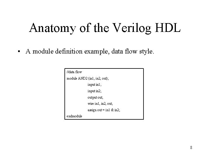
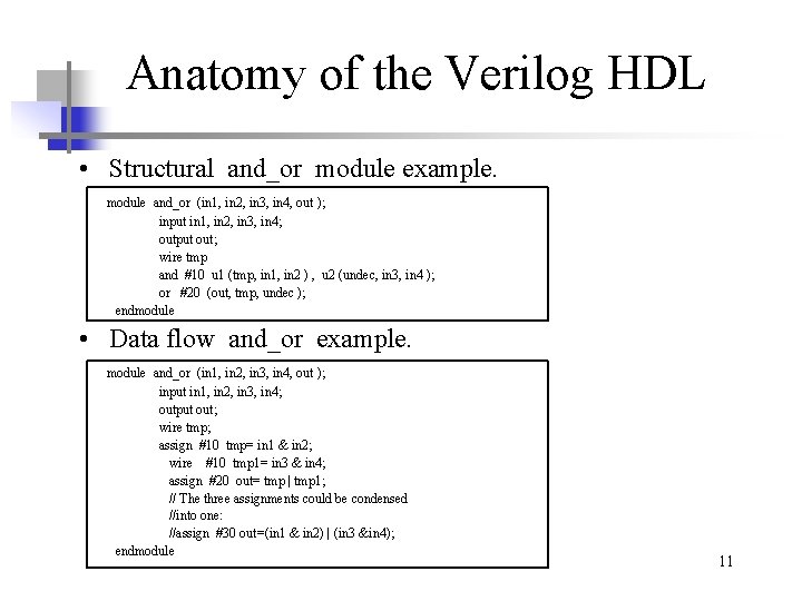
Data Flow Modelling in Verilog
Ansys Photonics Verilog-A. Specifications comes first they describe abstractly the functionality interface and the architecture of the digital IC circuit to be designed.
What Is The Difference Between Data Flow And Behavioral Modelling In Verilog Hdl Ee Vibes
Data-modeling business-process modeling - round trip engineering Prosa UML Modeller.
. GEneralized K-Omega turbulence model offers a flexible robust general purpose approach to RANS turbulence modelling. It is also known as a data selector. GDT is very important part of mechanical product design.
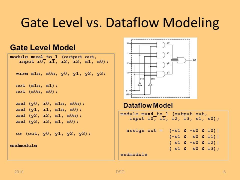
XRT supports Alveo PCIe -based cards as well as Versal and Zynq UltraScale MPSoC-based embedded system platforms and provides a software interface to Xilinx programmable logic devices. A multiplexer is a device that selects one output from multiple inputs. Multiplexers are used in communication systems to increase the amount of data sent over a network within a certain amount of time and bandwidth.
We refer to a multiplexer with the terms MUX and MPX. The Verilog does not have user-defined types and we are restricted to arrays of built-in Verilog types such as nets regs and other Verilog variable types. What is meant by GDT.
Geometric Dimension Tolerance GDT is a system for defining engineering tolerances. An array is a collection of the same types of variables and accessed using the same name plus one or more. The VLSI IC circuits design flow is shown in the figure below.
GDT defines degree of accuracy and precision required on controlled feature of part. Xilinx Runtime XRT is implemented as a combination of user-space and kernel driver components. Verilog arrays are used to group elements into multi-dimensional objects to be manipulated more easily.
Ansys simulation helps model the behavior of fluid flow as aircraft travel above hypersonic speed including strong shocks plasma and structural deformation. Part 1 of this video provides. Yes Yes Open modelbase Yes C Java C SQL DDL and SQL queries C Java and C class headers are synchronized between diagrams and code in real-time Programmers workbenches documentation tools version control systems.
The various levels of design are numbered and the blocks show processes in the design flow.
Digital Design And Synthesis With Verilog Hdl Eli
Digital System Design Verilog Hdl Dataflow Modeling Maziar Goudarzi Ppt Download
Digital Design And Synthesis With Verilog Hdl Eli

Digital System Design Verilog Hdl Dataflow Modeling Maziar Goudarzi Ppt Download
No comments for "Data Flow Modelling in Verilog"
Post a Comment